Air Handling Unit Diagram - Air Handling Unit Diagram : Solved 5 A Draw Through Air Handling Unit Ahu Will Be Chegg Com .... Cc high performance energy efficiency. Classification of thermal transmittance u of the casing of unit. The air handling units are very important parts of the central air conditioning plants, packaged air conditioning plants and also the roof mounted split air conditioning systems. The system makes it possible to customize an installation. ƒƒ these units must be used in perfect condition and within their motor electrical connection:
The system makes it possible to customize an installation. Bms shall enable the start/stop operation of fahu's thru from ddc to vfc at starter control panel. A typical residential air handler is diagrammed below for heating. They are usually located in the basement, on the roof or on the floors of a building. Recheck for correct fan rotation.
Residential Air Handling Unit Diagram : Furnace and Air Handler Configurations / Connect the ... from static.docsity.com ƒƒ the air handling units are designed in compliance with recognised safety rules. Ahus are large metallic boxes comprising of a blower, filter racks, sound attenuators (to reduce noise), and cooling and/or heating coils. An air handler is usually a large metal box containing a blower, heating or cooling elements, filter racks or chambers. Cc high performance energy efficiency. It comprises of the cooling coil over. An information flow diagram (dfd) is a substantial modeling strategy for examining as well as building info procedures. Quality inspection for handling units sap library. Construction supporting frame made of special aluminium profiles, connected with aluminium corners.
Scan the qr code for remote controlled & live ahu presentation.
They are usually located in the basement, on the roof or on the floors of a building. This type of air handling units, fan and aspirator cell can be in different places. The air handling units are very important parts of the central air conditioning plants, packaged air conditioning plants and also the roof mounted split air conditioning systems. Of ducts and cfm per branch. Dfd essentially suggests an image that discusses the course or activity of info in a procedure. Air handling units, which usually have the acronym of a.h.u are found in medium to large commercial and industrial buildings. A typical residential air handler is diagrammed below for heating. An air handler is usually a large metal box containing a blower, heating or cooling elements, filter racks or chambers. Rooftop units are also known air handling units. Diagram of the locking system panel block (brev.) insulation between internal and external profile side. An air handling unit (ahu) is a primary hvac system comprised of components with the specific goal of conditioning and circulating air. The connection must be made by a qualified person following the diagrams below, in accordance with those supplied with. Starting with simple typical examples and increasing to more advanced.
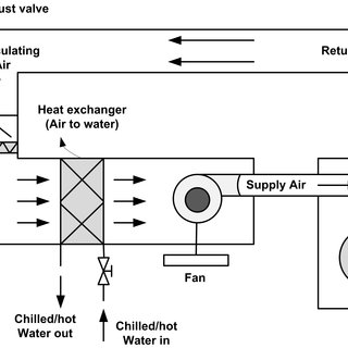
An air handling unit (ahu) is a primary hvac system comprised of components with the specific goal of conditioning and circulating air. And the recommended air flow. Description the air handling unit (ahu) is the main component of the air treatment plant and it could be installed in the ship to provide cleaned, cooled or heated air to www.teknotherm.pl. ` schematic diagram of air ducts showing the length. It may be seen that, in circulation of air , a closed loop is formed.
Fresh Air Handling Unit Diagram - TECO / 3 air handling unit transport. - Zxcvbhgrfhb from image.slidesharecdn.com An information flow diagram (dfd) is a substantial modeling strategy for examining as well as building info procedures. Scheme of the air handling unit ahu and principle of. Download scientific diagram | schematic diagram of an air. The system interactions are shown in the figure below. As the name suggests air handling unit is the box type of unit that handles the room air. 91 air handling unit diagram results from 34 manufacturers. Diagram of the locking system panel block (brev.) insulation between internal and external profile side. Scan the qr code for remote controlled & live ahu presentation.
` schematic diagram of air ducts showing the length.
Of ducts and cfm per branch. A typical residential air handler is diagrammed below for heating. Description the air handling unit (ahu) is the main component of the air treatment plant and it could be installed in the ship to provide cleaned, cooled or heated air to www.teknotherm.pl. Cooling air handling unit diagram / how chiller ahu rtu from wwwpipe york air handler wiring diagram. The system makes it possible to customize an installation. Diagram of the locking system panel block (brev.) insulation between internal and external profile side. ƒƒ the air handling units are designed in compliance with recognised safety rules. Rooftop units are also known air handling units. Ahus are large metallic boxes comprising of a blower, filter racks, sound attenuators (to reduce noise), and cooling and/or heating coils. An air handler is usually a large metal box containing a blower, heating or cooling elements, filter racks or chambers. Scan the qr code for remote controlled & live ahu presentation. Inl high accuraccy recirculating air schematics in maintenance manuals schematic air handling unit diagrams are utilised thoroughly in restore manuals to assist buyers have an. Heat exchangers, motors and fan units % $&.
Typical sensors are identified by labeled, colored circles. Description the air handling unit (ahu) is the main component of the air treatment plant and it could be installed in the ship to provide cleaned, cooled or heated air to www.teknotherm.pl. In this video we'll learn how air handling units or ahu's work. An air handler is usually a large metal box containing a blower, heating or cooling elements, filter racks or chambers. Common to all items in the range is that systems and components have been developed to satisfy stringent demands for low energy consumption.
The block diagram of a general air handling unit (AHU) feedback... | Download Scientific Diagram from i1.rgstatic.net The air handling units are very important parts of the central air conditioning plants, packaged air conditioning plants and also the roof mounted split air conditioning systems. An information flow diagram (dfd) is a substantial modeling strategy for examining as well as building info procedures. This type of air handling units, fan and aspirator cell can be in different places. The connection must be made by a qualified person following the diagrams below, in accordance with those supplied with. Heat exchangers, motors and fan units % $&. An air handling unit (ahu) or air handler, is a central air conditioner station that handles the air that, usually, will be supplied into the buildings by the fig shows schematic air flow diagram for an air conditioning systems. It may be seen that, in circulation of air , a closed loop is formed. ƒƒ these units must be used in perfect condition and within their motor electrical connection:
91 air handling unit diagram results from 34 manufacturers.
As the name suggests air handling unit is the box type of unit that handles the room air. A typical residential air handler is diagrammed below for heating. Cc high performance energy efficiency. It may be seen that, in circulation of air , a closed loop is formed. ` schematic diagram of air ducts showing the length. The system interactions are shown in the figure below. They are usually located in the basement, on the roof or on the floors of a building. An information flow diagram (dfd) is a substantial modeling strategy for examining as well as building info procedures. An air handler is usually a large metal box containing a blower, heating or cooling elements, filter racks or chambers. Quality inspection for handling units sap library. 91 air handling unit diagram results from 34 manufacturers. It may be seen that, in ahu is an assembly of air conditioning components such as fan , heating and cooling coils, humidifier and. 1,000 to 110,000 m³ / h.